


An Overview of Class 11 Physics To Measure Diameter Of A Given Wire Using Screw Gauge Experiment
Measurement is a common problem in both physics and engineering. Many times we are required to accurately measure extremely small lengths such as the diameter of a thin wire, the thickness of a sheet, etc. in construction and blueprint services. Any small miscalculation might lead to large errors in the measurement. Therefore, it becomes essential to get a simple hands-on way to measure the diameter of a given wire using a screw gauge.
Table of Contents
Aim
Theory
Procedure
Observations
Result
Aim
To measure the diameter of a given wire using a screw gauge.
Apparatus required
Given wire
Screw gauge
Magnifying glass
Theory
A screw gauge works using a main and a circular scale. The distance covered on the main scale by the circular scale after completing one full rotation is known as the pitch of the circular scale or pitch of screw gauge. In this experiment, we put the wire between the two rods of the main scale and gently tighten the rods using the screw of the circular scale. The corresponding readings on the main and circular scales give the measurement of the diameter of the wire.
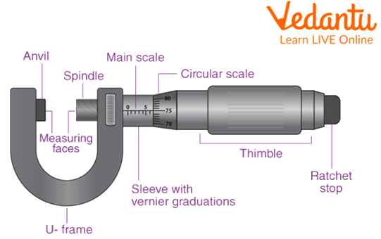
Schematic Diagram of Screw Gauge with its Components
Procedure
Rotate the circular scale so that it traverses towards the fixed end of the gauge, till it comes in contact with the end (Please refer to the image given above).
Check if the zero of circular scale coincides with the zero of main scale. If not, note the circular scale division that coincides best with the main engraved scale.
Now rotate the circular scale exactly once and note the division on the main scale with which the circular scale coincides to get the pitch.
Divide this distance by the number of divisions on a circular scale to get the least count.
Now, rotate the circular scale using a screw in the opposite direction and hold the wire between the two rods of the main scale. Hold the wire gently between the rods till the screw stops rotating.
Note the main scale reading where the circular scale lies using a magnifying glass.
Note the circular scale reading, which coincides with the main scale.
Loosen the circular scale screw and note both readings in a similar fashion two other times. Note the observations.
Observations
Pitch of the screw gauge = 1 mm
Number of divisions on circular scale = 100
Least count = \[\dfrac{\text{Pitch}}{\text{Number of divisions}}\; = \dfrac{{1\;mm}}{{100}} = 0.01\;mm\]
Observation Table
Result
Average diameter of the wire,
D =\[\dfrac{{D_1 + D_2 + D_3}}{3} = …………\]
Precautions
Note the zero error very carefully.
Do not hold the wire using the gauge too tightly or too loosely.
Only note the circular scale division which coincides best with the main scale using magnifying glass. If no division is coinciding, note the preceding division.
Lab Manual Questions
1. Out of two screw gauges having 100 and 300 divisions respectively, which should be preferred for taking readings and why?
Ans: Out of these two screw gauges, the one with 300 divisions on the circular scale should be preferred for taking readings. This is because the least count of a screw gauge is inversely proportional to the circular scale divisions, and more accuracy can be reached with decreasing the least count.
2. How to solve the instrumental error arising when the linear distance moved by the screw is not proportional to the rotation given to it?
Ans: In such situations, the screw becomes torn out from the inside and develops a lot of irregularities. It is advisable to replace the screw.
3. Explain the scales of the screw gauge? How does a zero error arise?
Ans: A screw gauge has two scales - one is the main scale and another one is a circular scale with 100 divisions engraved on it. When the zero error of the circular scale does not coincide with the zero of the main scale, zero error arises.
4. Why does a screw gauge develop a backlash error after some time?
Ans: Due to wear and tear of the instrument, a screw gauge develops a backlash error after some time due to the development of numerous irregularities inside the circular scale.
Viva Questions
1. Explain the working principle of a screw gauge.
Ans: A screw gauge is based on the principle of a rotating screw. As the screw rotates, it covers a linear distance on the main scale. This gives us the pitch and least count and hence the required accuracy for measurement.
2. What are the orders of length a screw gauge is suitable for measuring?
Ans: A screw gauge is capable of precisely measuring lengths up to 0.01 mm.
3. Why is a screw gauge called a micrometer gauge?
Ans: The precision up to which a screw gauge can measure is 0.01 mm and it is equivalent to the 10 µm, therefore, as we can see it lies in the range of micrometer the screw gauge is also called a micrometer gauge.
4. Write three commercial applications of a screw gauge.
Ans: Screw gauge finds commercial applications in precisely determining the diameter of thin wires, the thickness of a paper sheet and the thickness of a given experimental metallic chip used in communication devices.
5. Explain the formula for the calculation of least count.
Ans: Least count is calculated by dividing the distance covered by the circular scale on its one full rotation on the main scale (pitch) by the number of divisions on the circular scale.
6. Explain zero error. How to determine zero error?
Ans: A zero error is the error which arises in the final result when the zeroes of the main scale and circular scale do not coincide. It is determined by noting the main scale division with which the circular scale coincides at the full range of rotation of the circular scale.
7. How is a screw gauge better than a vernier calliper?
Ans: A screw gauge has a greater precision of 0.01 mm of measuring lengths compared to vernier calipers (0.1 mm). Hence, the lengths measured by a screw gauge are more accurate to a second decimal than a vernier calliper.
8. Give the working formula of a screw gauge.
Ans: The final reading is given by the sum of main scale and circular scale readings, which is given by the product of the number of coinciding circular scale divisions and the least count of the instrument.
9. What is pitch?
Ans: The length covered by the circular scale over the main scale on one complete rotation of the circular scale is known as the pitch of the instrument. It is roughly equal to 1 mm.
10. Name two other examples that can be used alternatively in the above experiment.
Ans: The thickness of the sheet of paper and the diameter of a thin stick can also be used in the above experiment.
Practical Based Questions
1. Least count of screw gauge is:
1 mm
0.1 mm
0.01 mm
0.001 mm
Ans: (C) The least count of a screw gauge is 0.01 mm.
2. How many screws are there in a screw gauge?
1
2
3
4
Ans: (A) A screw gauge has 1 screw for the movable hinge.
3. How many scales does a screw gauge have?
2
3
5
6
Ans: (A) A screw gauge has 2 scales
4. The ratio of the least counts of the centimeter scale to that of a screw gauge is:
1
10
100
1000
Ans: (C) The least count of a centimeter scale is 1 mm, while that of a screw gauge is 0.01 mm. Hence the ratio is 100.
5. Screw gauge is ideal for measuring:
Edge of a dice
Thickness of a wire
Radius of curvature
Length of a notebook
Ans: (B) A screw gauge can be used to accurately measure the thickness of a wire.
6. A screw gauge can be manufactured by a combination of:
Copper and tin
Aluminum
Stainless steel and iron
None of the above
Ans: (C) A screw gauge can be manufactured by a combination of stainless steel and iron.
7. The error that arises when the zeroes of the main scale and the circular scale do not coincide is called:
Systematic error
Random error
Backlash error
Zero error
Ans: (D) The error that arises when the zeroes of main and circular scales do not coincide is called zero error.
8. Accuracy of measurement can be increased by:
Increasing the number of divisions on circular scale
Using a magnifying glass
Using a thick wire for measuring diameter
Using more circular scales
Ans: (A) The accuracy of measurement can be increased by increasing the number of divisions on a circular scale.
9. How many types of zero errors are there?
One
Two
Three
Four
Ans: (B) There are two types of zero errors - positive and negative.
10. Which of the following is not suitable for measurement by a screw gauge?
Diameter of a thin wire
Thickness of a fine slab
Depth of a vessel
Thickness of a semiconductor chip
Ans: (C) Depth of a vessel is not suitable for measurement by a screw gauge.
Conclusion
From this experiment, we can conclude that screw gauge finds immense applications in the field of experimental physics in order to accurately measure the diameter of thin wires, the thickness of a sheet etc. They find various commercial applications in numerous engineering and medical fields in the society.
Throughout this experiment, we have taken utmost care in teaching the novice about the very idea, and the basic parameters should have been crystal clear in his/ her mind.
We hope that the reader is now enlightened regarding the very concept of the same and is motivated to explore the field in the time to come.
FAQs on Class 11 Physics To Measure Diameter Of A Given Wire Using Screw Gauge Experiment
1. For the CBSE Class 11 Physics practical exam, define the terms 'pitch' and 'least count' of a screw gauge.
In the context of a screw gauge, the pitch is the linear distance the screw moves along the main scale during one complete rotation of the circular scale. The least count (LC) is the smallest value that can be accurately measured by the instrument and is calculated by dividing the pitch by the total number of divisions on the circular scale. It represents the precision of the screw gauge.
2. What is meant by zero error in a screw gauge? From an exam perspective, explain the difference between positive and negative zero error.
A zero error occurs when the zero mark of the circular scale does not coincide with the baseline of the main scale when the jaws are closed. It is an important parameter to check for accurate measurements.
- Positive Zero Error: Occurs when the zero of the circular scale is below the baseline. The error is positive and is subtracted from the final observed reading.
- Negative Zero Error: Occurs when the zero of the circular scale is above the baseline. The error is negative, and its magnitude is added to the final observed reading during correction.
3. State the formula used to calculate the diameter of a wire with a screw gauge and explain each term. Why is this formula crucial for scoring full marks in calculations?
The formula to calculate the observed diameter is:
Observed Diameter = MSR + (CSD × LC)
Where:
- MSR stands for Main Scale Reading, which is the last visible reading on the linear main scale.
- CSD is the Circular Scale Division that aligns perfectly with the main scale's baseline.
- LC is the Least Count of the screw gauge.
This formula is essential because it correctly combines the main scale measurement with the more precise circular scale measurement, which is a required step in the exam.
4. A student measures a wire's diameter and finds the Main Scale Reading (MSR) is 2 mm and the 65th division of the circular scale coincides with the baseline. If the least count is 0.01 mm and there is a positive zero error of +0.04 mm, calculate the correct diameter of the wire.
To find the correct diameter, we first calculate the observed diameter and then apply the zero correction.
1. Observed Diameter = MSR + (CSD × LC)
= 2 mm + (65 × 0.01 mm) = 2 mm + 0.65 mm = 2.65 mm.
2. Correct Diameter = Observed Diameter – Zero Error
= 2.65 mm – (+0.04 mm) = 2.61 mm.
Therefore, the correct diameter of the wire is 2.61 mm.
5. What are three important precautions a student must take while using a screw gauge to measure a wire's diameter to avoid common errors?
Three important precautions for accurate measurements are:
- Always check for zero error before taking measurements and apply the necessary correction.
- To avoid backlash error, the screw should be rotated in only one direction when making a final adjustment.
- Use the ratchet to tighten the screw. This prevents applying excessive pressure on the wire, which could deform it and lead to an incorrect reading.
6. Why is it an important experimental practice to measure the wire's diameter at several different points and along mutually perpendicular axes?
This practice is crucial for two main reasons:
1. To account for any non-uniformity in the wire's thickness. The wire may not have the same diameter along its entire length.
2. To check if the wire's cross-section is perfectly circular. Measuring along perpendicular axes (e.g., horizontal and vertical) and averaging the results helps to nullify the effect of any oval shape.
This ensures the calculated average diameter is a more accurate and representative value for the entire wire.
7. What is backlash error in a screw gauge and what is the best technique to minimise it during the experiment?
Backlash error is a mechanical error caused by a lag or gap between the rotation of the screw and the movement of the spindle, often due to wear and tear in the screw mechanism. This means the spindle might not move linearly even when the thimble is turned. The best technique to minimise this error is to always approach the final measurement by turning the thimble in the same direction, preferably clockwise, without turning it back and forth.
8. How can a significant change in room temperature during the Class 11 experiment affect the accuracy of the screw gauge reading? Explain the underlying physics principle.
A significant change in temperature can affect accuracy due to the principle of thermal expansion. If the temperature rises, the metallic components of the screw gauge, including the main frame and the screw, will expand. This expansion can slightly alter the pitch and the zero setting of the instrument, leading to systematic errors in the measurement. Conversely, a drop in temperature can cause contraction, also affecting the reading. Therefore, experiments requiring high precision should be conducted in a temperature-controlled environment.
9. For 2 marks, differentiate between a screw gauge and a Vernier caliper based on their precision and typical applications.
The key differences are:
- Precision: A screw gauge is more precise, with a typical least count of 0.01 mm, making it suitable for very small measurements. A Vernier caliper is less precise, with a typical least count of 0.1 mm.
- Application: A screw gauge is used to measure the diameter of thin wires or the thickness of paper sheets. A Vernier caliper is used for measuring larger dimensions, such as the length of a rod, the diameter of a beaker, or the depth of a small vessel.