


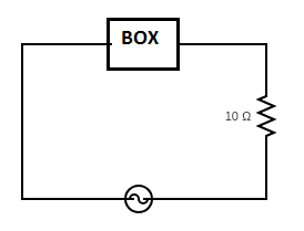
In the circuit shown in the figure power factor of the box is $0.5$ and the power factor of the circuit is $\dfrac{{\sqrt 3 }}{2}$. The current is leading the voltage. Find the effective resistance (in ohms) of the box.
Answer
526.5k+ views
Hint: Capacitance opposes the change in voltage and serves to delay the increase or decrease of voltage across the capacitor. This causes the voltage to lag behind the current in a capacitive circuit. When L or C is present in an ac circuit, energy is required to build up a magnetic field around L or an electric field in C. This energy comes from the source.
Complete step by step answer:
Given, power factor of the box is given by, $\cos {\phi _{box}} = 0.5$
Then, ${\phi _{box}} = {\cos ^{ - 1}}(0.5)$
$ \Rightarrow {\phi _{box}} = {60^0}$
Similarly, power factor of the circuit is given by, $\cos {\phi _{circuit}} = \dfrac{{\sqrt 3 }}{2}$
Then, ${\phi _{circuit}} = {\cos ^{ - 1}}(\dfrac{{\sqrt 3 }}{2})$
$ \Rightarrow {\phi _{circuit}} = {30^0}$
Given, resistance in the circuit $R = 10\Omega $
Here we need to find the resistance to the box.
Let ${R_{box}}$ be the effective resistance of the box.
It is given in the question that the current is leading the voltage. From this, we can say that the given circuit is a purely capacitive circuit.
Then$\tan {\phi _{box}} = \dfrac{{{X_c}}}{{{R_{box}}}}$
Where ${X_C}$ is the reactive capacitance of the circuit.
We have, ${\phi _{box}} = {60^0}$and $\tan {60^0} = \sqrt 3 $ then
Above equation becomes, $\sqrt 3 = \dfrac{{{X_c}}}{{{R_{box}}}}$
$ \Rightarrow {X_C} = \sqrt 3 {R_{box}}$ ………………..(1)
Similarly,
$ \Rightarrow \tan {\phi _{circuit}} = \dfrac{{{X_c}}}{{{R_{circuit}} + {R_{box}}}}$
We have, ${\phi _{box}} = {30^0}$and $\tan {30^0} = \dfrac{1}{{\sqrt 3 }}$
Then the above equation becomes,
$ \Rightarrow \dfrac{1}{{\sqrt 3 }} = \dfrac{{{X_c}}}{{{R_{circuit}} + {R_{box}}}}$
$ \Rightarrow {X_c} = \dfrac{{{R_{circuit}} + {R_{box}}}}{{\sqrt 3 }}$
We can substitute the values in the equation we get,
$ \Rightarrow {X_c} = \dfrac{{10 + {R_{box}}}}{{\sqrt 3 }}$ ……………………(2)
Compare equation (1) and (2) we get,
$ \Rightarrow \sqrt 3 {R_{box}} = \dfrac{{10 + {R_{box}}}}{{\sqrt 3 }}$
Simplifying the above equation we get,
$ \Rightarrow \sqrt 3 \times \sqrt 3 {R_{box}} = 10 + {R_{box}}$
$ \Rightarrow 3{R_{box}} = 10 + {R_{box}}$
$\therefore {R_{box}} = 5\Omega $
Therefore, the effective resistance (in ohms) of the box is $5\Omega $.
Note:
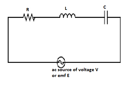
Consider a circuit containing an inductor, capacitor and resistor connected in series across an alternating source of voltage $V$ or emf $\varepsilon $ .
Let the source supplies a sinusoidal voltage which is given by,
$V = {V_0}\sin \omega t$
Where, ${V_0}$ is the peak value of voltage $\omega $ is the angular frequency and $t$ is the time period.
Let $q$ be the charge on the capacitor and $I$ be the current in the circuit at any instant of time $t$.
Let${V_R},{V_L},{V_C}$ represent the voltage across the resistor, inductor, and capacitor respectively.
Then, voltage across resistor, ${V_R} = {i_0}R$
Voltage across inductor, ${V_L} = {i_0}{X_L}$
Voltage across capacitor, ${V_C} = {i_0}{X_C}$
Where, ${i_0}$ is the peak value of current, ${X_C}$ is capacitive reactance, ${X_L}$ is the inductive reactance and $R$ is the resistance of the resistor.
Then net voltage or emf is given by, $V$ or $\varepsilon = \sqrt {\left( {{V_R}^2 + {{\left( {{V_L} - {V_C}} \right)}^2}} \right)} $
Complete step by step answer:
Given, power factor of the box is given by, $\cos {\phi _{box}} = 0.5$
Then, ${\phi _{box}} = {\cos ^{ - 1}}(0.5)$
$ \Rightarrow {\phi _{box}} = {60^0}$
Similarly, power factor of the circuit is given by, $\cos {\phi _{circuit}} = \dfrac{{\sqrt 3 }}{2}$
Then, ${\phi _{circuit}} = {\cos ^{ - 1}}(\dfrac{{\sqrt 3 }}{2})$
$ \Rightarrow {\phi _{circuit}} = {30^0}$
Given, resistance in the circuit $R = 10\Omega $
Here we need to find the resistance to the box.
Let ${R_{box}}$ be the effective resistance of the box.
It is given in the question that the current is leading the voltage. From this, we can say that the given circuit is a purely capacitive circuit.
Then$\tan {\phi _{box}} = \dfrac{{{X_c}}}{{{R_{box}}}}$
Where ${X_C}$ is the reactive capacitance of the circuit.
We have, ${\phi _{box}} = {60^0}$and $\tan {60^0} = \sqrt 3 $ then
Above equation becomes, $\sqrt 3 = \dfrac{{{X_c}}}{{{R_{box}}}}$
$ \Rightarrow {X_C} = \sqrt 3 {R_{box}}$ ………………..(1)
Similarly,
$ \Rightarrow \tan {\phi _{circuit}} = \dfrac{{{X_c}}}{{{R_{circuit}} + {R_{box}}}}$
We have, ${\phi _{box}} = {30^0}$and $\tan {30^0} = \dfrac{1}{{\sqrt 3 }}$
Then the above equation becomes,
$ \Rightarrow \dfrac{1}{{\sqrt 3 }} = \dfrac{{{X_c}}}{{{R_{circuit}} + {R_{box}}}}$
$ \Rightarrow {X_c} = \dfrac{{{R_{circuit}} + {R_{box}}}}{{\sqrt 3 }}$
We can substitute the values in the equation we get,
$ \Rightarrow {X_c} = \dfrac{{10 + {R_{box}}}}{{\sqrt 3 }}$ ……………………(2)
Compare equation (1) and (2) we get,
$ \Rightarrow \sqrt 3 {R_{box}} = \dfrac{{10 + {R_{box}}}}{{\sqrt 3 }}$
Simplifying the above equation we get,
$ \Rightarrow \sqrt 3 \times \sqrt 3 {R_{box}} = 10 + {R_{box}}$
$ \Rightarrow 3{R_{box}} = 10 + {R_{box}}$
$\therefore {R_{box}} = 5\Omega $
Therefore, the effective resistance (in ohms) of the box is $5\Omega $.
Note:
Consider a circuit containing an inductor, capacitor and resistor connected in series across an alternating source of voltage $V$ or emf $\varepsilon $ .
Let the source supplies a sinusoidal voltage which is given by,
$V = {V_0}\sin \omega t$
Where, ${V_0}$ is the peak value of voltage $\omega $ is the angular frequency and $t$ is the time period.
Let $q$ be the charge on the capacitor and $I$ be the current in the circuit at any instant of time $t$.
Let${V_R},{V_L},{V_C}$ represent the voltage across the resistor, inductor, and capacitor respectively.
Then, voltage across resistor, ${V_R} = {i_0}R$
Voltage across inductor, ${V_L} = {i_0}{X_L}$
Voltage across capacitor, ${V_C} = {i_0}{X_C}$
Where, ${i_0}$ is the peak value of current, ${X_C}$ is capacitive reactance, ${X_L}$ is the inductive reactance and $R$ is the resistance of the resistor.
Then net voltage or emf is given by, $V$ or $\varepsilon = \sqrt {\left( {{V_R}^2 + {{\left( {{V_L} - {V_C}} \right)}^2}} \right)} $
Recently Updated Pages
Master Class 12 Business Studies: Engaging Questions & Answers for Success
Master Class 12 Economics: Engaging Questions & Answers for Success
Master Class 12 English: Engaging Questions & Answers for Success
Master Class 12 Maths: Engaging Questions & Answers for Success
Master Class 12 Social Science: Engaging Questions & Answers for Success
Master Class 12 Chemistry: Engaging Questions & Answers for Success
Trending doubts
Which are the Top 10 Largest Countries of the World?
Differentiate between homogeneous and heterogeneous class 12 chemistry CBSE
Why is the cell called the structural and functional class 12 biology CBSE
Who discovered the cell and how class 12 biology CBSE
What is the Full Form of PVC, PET, HDPE, LDPE, PP and PS ?
Derive an expression for electric potential at point class 12 physics CBSE