


State Kirchhoff’s law of electrical circuits with the help of a suitable circuit diagram. Write the formula of zero deflection of the Wheatstone bridge.
Answer
531.3k+ views
Hint: There are two laws proposed by Kirchhoff to find the current flowing through ‘a’ various conductors or to find the equivalent resistance of the conductors of a complicated circuit. Herewith a suitable diagram we will state the laws. With the help of the laws, we can derive an equation for the zero deflection in the Wheatstone bridge.
Formula used:
\[\begin{align}
& \sum{I}=0 \\
&\Rightarrow \sum{V}=0 \\
&\Rightarrow \dfrac{R}{P}=\dfrac{S}{Q} \\
\end{align}\]
Complete step-by-step solution:
There are two laws stated by Kirchhoff known as
1) Junction rule or Kirchhoff’s current law (KCL): According to Kirchhoff’s current law, the incoming current is equal to the current leaving the node or the junction. Let us understand this with the help of a circuit diagram as shown below
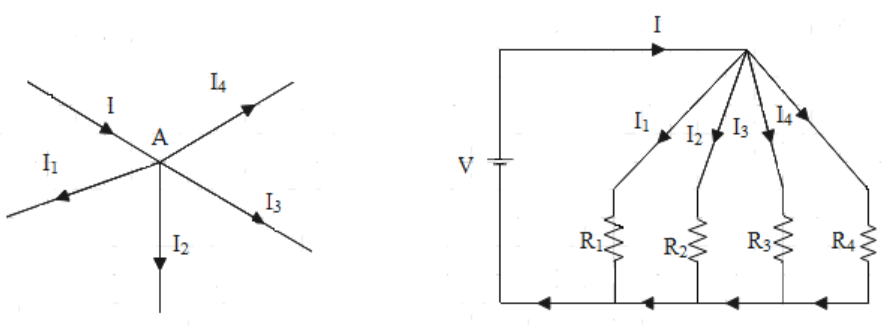
Here at node A or junction A, current I is entering and \[{{I}_{1}},\text{ }{{I}_{2}},\text{ }{{I}_{3}},\text{ and }{{I}_{4}}\]is leaving the junction. Assuming the current entering positive and current leaving junction A negative, from the law we have
\[\begin{align}
& I+\left( -{{I}_{1}} \right)+\left( -{{I}_{2}} \right)+\left( -{{I}_{3}} \right)+\left( -{{I}_{4}} \right)=0 \\
&\Rightarrow I={{I}_{1}}+{{I}_{2}}+{{I}_{3}}+{{I}_{4}} \\
\end{align}\]
Hence we can write the Kirchhoff’s current law as
\[\sum{I}=0\]
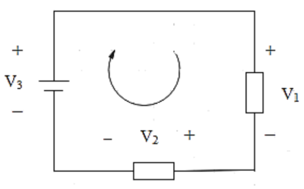
2) Loop rule or Kirchhoff’s voltage law (KVL): According to Kirchhoff’s voltage law, the sum of voltage in a loop is zero. Consider the following diagram
Then the voltage in the loop can be given as
\[\begin{align}
& -{{V}_{3}}+{{V}_{1}}+{{V}_{2}}=0 \\
&\Rightarrow {{V}_{1}}+{{V}_{2}}={{V}_{3}} \\
\end{align}\]
Hence, the loop rule can be written as
\[\sum{V}=0\]
Let us now derive a formula for the null deflection in the Wheatstone bridge. A circuit diagram for the Wheatstone bridge is given as
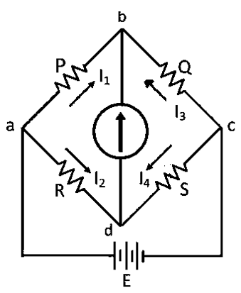
Applying junction rule at node b and d respectively, we get\[{{I}_{1}}={{I}_{3}}\text{ and }{{I}_{2}}={{I}_{4}}\] respectively.
Assume current flowing through the galvanometer, \[{{I}_{g}}=0\]
Applying loop rule to closed loop adba, we get
\[\begin{align}
& -{{I}_{2}}R+{{I}_{g}}+{{I}_{1}}P=0 \\
&\Rightarrow -{{I}_{2}}R+{{I}_{1}}P=0 \\
&\Rightarrow {{I}_{1}}P={{I}_{2}}R \\
&\Rightarrow \dfrac{{{I}_{1}}}{{{I}_{2}}}=\dfrac{R}{P} \\
\end{align}\]
Now applying loop rule to closed loop cbdc, we get
\[\begin{align}
& {{I}_{3}}Q+{{I}_{g}}-{{I}_{4}}S=0 \\
&\Rightarrow {{I}_{3}}Q-{{I}_{4}}S=0 \\
&\Rightarrow {{I}_{3}}Q={{I}_{4}}S \\
&\Rightarrow \dfrac{{{I}_{3}}}{{{I}_{4}}}=\dfrac{S}{Q} \\
\end{align}\]
As \[{{I}_{1}}={{I}_{3}}\text{ and }{{I}_{2}}={{I}_{4}}\]by junction rule, hence we can write
\[\begin{align}
& \dfrac{{{I}_{1}}}{{{I}_{2}}}=\dfrac{S}{Q} \\
&\Rightarrow \dfrac{R}{P}=\dfrac{S}{Q} \\
\end{align}\]
This last equation is the formula for the zero deflection in the galvanometer in terms of four resistors.
Note: Junction rule is also called point rule and the loop rule is also called mesh rule. The loop is certain as the electric potential is dependent on the location of the point, hence when we come to the same point, the total change should be zero.
While deriving the formula for the null deflection in the Wheatstone bridge we have to take or assume that the internal resistance is zero.
Formula used:
\[\begin{align}
& \sum{I}=0 \\
&\Rightarrow \sum{V}=0 \\
&\Rightarrow \dfrac{R}{P}=\dfrac{S}{Q} \\
\end{align}\]
Complete step-by-step solution:
There are two laws stated by Kirchhoff known as
1) Junction rule or Kirchhoff’s current law (KCL): According to Kirchhoff’s current law, the incoming current is equal to the current leaving the node or the junction. Let us understand this with the help of a circuit diagram as shown below
Here at node A or junction A, current I is entering and \[{{I}_{1}},\text{ }{{I}_{2}},\text{ }{{I}_{3}},\text{ and }{{I}_{4}}\]is leaving the junction. Assuming the current entering positive and current leaving junction A negative, from the law we have
\[\begin{align}
& I+\left( -{{I}_{1}} \right)+\left( -{{I}_{2}} \right)+\left( -{{I}_{3}} \right)+\left( -{{I}_{4}} \right)=0 \\
&\Rightarrow I={{I}_{1}}+{{I}_{2}}+{{I}_{3}}+{{I}_{4}} \\
\end{align}\]
Hence we can write the Kirchhoff’s current law as
\[\sum{I}=0\]
2) Loop rule or Kirchhoff’s voltage law (KVL): According to Kirchhoff’s voltage law, the sum of voltage in a loop is zero. Consider the following diagram
Then the voltage in the loop can be given as
\[\begin{align}
& -{{V}_{3}}+{{V}_{1}}+{{V}_{2}}=0 \\
&\Rightarrow {{V}_{1}}+{{V}_{2}}={{V}_{3}} \\
\end{align}\]
Hence, the loop rule can be written as
\[\sum{V}=0\]
Let us now derive a formula for the null deflection in the Wheatstone bridge. A circuit diagram for the Wheatstone bridge is given as
Applying junction rule at node b and d respectively, we get\[{{I}_{1}}={{I}_{3}}\text{ and }{{I}_{2}}={{I}_{4}}\] respectively.
Assume current flowing through the galvanometer, \[{{I}_{g}}=0\]
Applying loop rule to closed loop adba, we get
\[\begin{align}
& -{{I}_{2}}R+{{I}_{g}}+{{I}_{1}}P=0 \\
&\Rightarrow -{{I}_{2}}R+{{I}_{1}}P=0 \\
&\Rightarrow {{I}_{1}}P={{I}_{2}}R \\
&\Rightarrow \dfrac{{{I}_{1}}}{{{I}_{2}}}=\dfrac{R}{P} \\
\end{align}\]
Now applying loop rule to closed loop cbdc, we get
\[\begin{align}
& {{I}_{3}}Q+{{I}_{g}}-{{I}_{4}}S=0 \\
&\Rightarrow {{I}_{3}}Q-{{I}_{4}}S=0 \\
&\Rightarrow {{I}_{3}}Q={{I}_{4}}S \\
&\Rightarrow \dfrac{{{I}_{3}}}{{{I}_{4}}}=\dfrac{S}{Q} \\
\end{align}\]
As \[{{I}_{1}}={{I}_{3}}\text{ and }{{I}_{2}}={{I}_{4}}\]by junction rule, hence we can write
\[\begin{align}
& \dfrac{{{I}_{1}}}{{{I}_{2}}}=\dfrac{S}{Q} \\
&\Rightarrow \dfrac{R}{P}=\dfrac{S}{Q} \\
\end{align}\]
This last equation is the formula for the zero deflection in the galvanometer in terms of four resistors.
Note: Junction rule is also called point rule and the loop rule is also called mesh rule. The loop is certain as the electric potential is dependent on the location of the point, hence when we come to the same point, the total change should be zero.
While deriving the formula for the null deflection in the Wheatstone bridge we have to take or assume that the internal resistance is zero.
Recently Updated Pages
Master Class 12 Business Studies: Engaging Questions & Answers for Success
Master Class 12 Biology: Engaging Questions & Answers for Success
Master Class 12 Physics: Engaging Questions & Answers for Success
Class 12 Question and Answer - Your Ultimate Solutions Guide
Master Class 12 English: Engaging Questions & Answers for Success
Master Class 12 Economics: Engaging Questions & Answers for Success
Trending doubts
Which are the Top 10 Largest Countries of the World?
What is transplantation in agriculture class 12 biology CBSE
Differentiate between homogeneous and heterogeneous class 12 chemistry CBSE
Why is the cell called the structural and functional class 12 biology CBSE
Who discovered the cell and how class 12 biology CBSE
What is the Full Form of PVC, PET, HDPE, LDPE, PP and PS ?